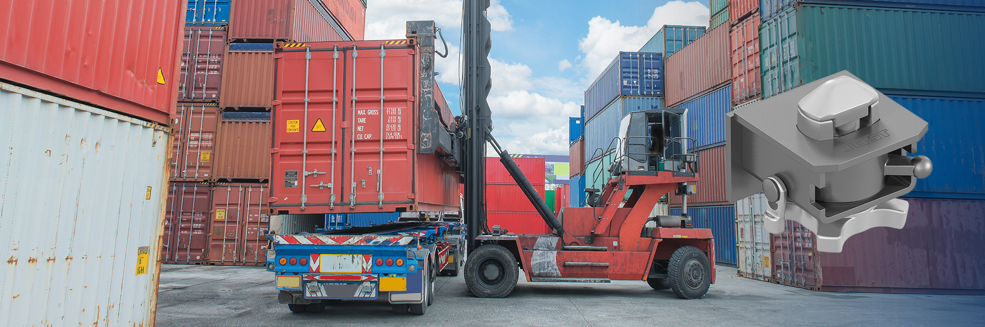
Twist locks

Twist locks

Flexibility, compatibility, stability and safety are thebasic parameters for a 
future-oriented motor pool. JOST ensures that these parameters can be satisfied 
 with its international quality standards and a global sales and after sales service 
 network. Twist locks connect containers to the carrier vehicle. The twist locks 
 must always be used as set out in the instructions in the operating manual for 
 the relevant vehicle. In Germany you must comply with the TÜV regulations 
 and the Road Traffic ActStVZO, as well as the existing standards. 

Videos

PDF-Downloads

Flyer
Components for Intermodal Transport Efficient logistc operations and reduced costs 10/2021
Container tipping chassis Twist locks and landing gear 08/2022
HV 120 V 09/2008

Pictures

Twist lock F17SKA-70

Twist lock FD02SK-RV

Twist lock F10SK-RV

Twist lock VA11SK

Twist lock R316VAP

Twist lock FB55HLL

Twist lock VA01SK

Twist lock R414F

Twist lock R416VAK

Twist lock R402F-R

Twist lock R401VAK

Twist lock R305VAP

Twist lock R405VAN

Twist lock R406VAK

Twist lock R405VAK

Twist lock R436VAK

Twist lock R402FQ-R

Twist lock R1018VAR

Twist lock R1018VAL

Twist lock F02EINZ002 soft

Twist lock F02EINZ002

Twist lock R301HVCLZ120

Twist lock R302HVCRZ120

Twist lock R316ZWEI07R soft

Twist lock R316ZWEI07R

Twist lock R1018VA-2

Twist lock R305HVCRZ120

Twist lock FB89-06VAV

Twist lock FB88-14V

Twist lock HV120V

Twist lock QA38NS

Twist lock VA36SK

Twist lock R306HVCR120

Twist lock R403FL

Twist lock FB90F

Twist lock R408F

Twist lock R305HVCRZ12LD

Twist lock FB91NS

Twist lock R305HVEL120D

Twist lock TS2009L-G

Twist lock R434F

Twist lock FB90-06VAV

Twist lock F02SK-R

Twist lock QA 37 N-1

Product range of non-retractable twist locks

rec. gross container weight max. (kg)*

Export version (cannot be screwed down)

Container chassis

Intermodal vehicle

S = sheet steel housing G = cast housing

Locking pin (mm)

Welding dimension (mm)

Back plate (mm)

Weight (kg)

Order No.

Drawing No.

34.000


G

ø 52

105

180x120

14.3

FD 02 SK-RV

905.165.000


G

ø 52

105

180x140

13.0

F 02 SK-R

905.162.000


S

ø 52

105

180x125

13.9

R 402 F-R

905.282.000


S

ø 52

95


12.1

R 302 F-R

905.281.000

30.500


S

ø 38

80

180x125

10.3

R 414 F

905.234.000


S

ø 38

72


9.0

R 314 F

905.199.000


S

ø 38

105

180x125

11.5

R 434 F

905.347.000


S

ø 38

95


09.8

R 334 F

905.354.000


S

ø 52

105

180x125

12.2

R 408 F

905.717.000


S

ø 52

95


10.5

R 308 F

905.716.000


G

ø 38

80

140x70

07.6

F 17 SKA-70 V

905.137.000

Special applications


34.000


S

ø 52

105

180x125

13.9

R 402 FQ-R

905.387.000


S

ø 52

105

207x135

18.3

R 403 FR

905.706.010


S

ø 52

105

207x135

18.3

R 403 FL

905.706.020

10.000


G

ø 38

80

150x85

7.0

F 10 SK-R**

905.188.000

* Depends on the centre to centre distance between the longitudinal supports

Note: 
All bolsters are delivered unmounted.
All twist locks can be screwed.

All spare parts with item number 915.xxx.xxx are zinc-plated.


Information for the vehicle construction:
** For type F10 SK-R and type VA 11, the locking pin is not compatible with the base opening of corner castings in accordance with ISO 1161. This type is only be used with the CC 012 corner casting.
All spare parts with item number 915.xxx.xxx are zinc-plated.

Indications for mounting of the locking ring:
• For the installation of the locking ring an appopriate tool has to be used.
• Intallation tool locking ring, please see chapter Installation tool for locking rings.
• The locking ring has principally to be replaced after dismantling the inner part of the twist lock.

(•) only in centre position

Product range of retractable twist locks

rec. gross container weight* max. (kg)

Export version (cannot be screwed down)

Container chassis

Intermodal vehicle / trailer

Platform

S = sheet steel housing G = cast housing

Locking pin

Welding dimension (mm)

Back plate (mm)

Weight (kg)

Order No.

Drawing No.

34.000


S

ø 52

105

180x125

16.4

R 401 VAK

905.294.000


S

ø 52

95

14.7

R 301 VA

905.222.000


G

ø 52

105

180x140

16.2

VA 01 SK

905.207.000

30.500


S

ø 38

155


15.7

R 316 VAP

905.202.000

25.400


S

ø 52

105

180x125

12.2

R 405 VAK

905.319.000


S

ø 52

95

10.5

R 305 VA

905.273.000


S

ø 38

105

180x125

11.6

R 406 VAK

905.317.000


(•)


S

ø 38

105

180x125

11.8

R 406 VAK-C

905.561.000


S

ø 38

95

9.8

R 306 VA

905.315.000


S

ø 52

105

180x 70

10.8

R 405 VAN

905.400.000


S

ø 52

95

9.8

R 305 VAN

905.413.000


S

ø 52

155

14.0

R 305 VAP

905.295.000


(•)


S

ø 38

80

180x125

10.5

R 416 VAK

905.248.000


(•)


S

ø 38

72

9.2

R 316 VA

905.198.000


(•)


S

ø 38

105

180x125

11.7

R 436 VAK

905.346.000


(•)


S

ø 38

95

10.0

R 336 VA

905.353.000


(•)

S

ø 38

105

180x130

12.9

R 1018 VAR

905.429.010


(•)

S

ø 38

105

180x130

12.9

R 1018 VAL

905.429.020


S

ø 38

105

330x125

25.2

R 1018 VA-2

905.614.000


(•)


G

ø 38

105

180x125

11.7

VA 36 SK

905.691.000


(•)


G

ø 38

60

150x140

7.9

QA 37 NS

905.674.000


(•)


G

ø 38

60

150x140

8.5

QA 37 NS-1

905.667.000


(•)


G

ø 38

80

150x110

8.4

QA 38 NS

905.675.000


(•)


G

ø 38

80

150x110

9.0

QA 38 NS-1

905.676.000


(•)


G

ø 38

125

185x90

13.1

TL 2009 R-G

905.926.010


(•)


G

ø 38

125

185x90

13.1

TL 2009 L-G

905.926.020

10.000


G

ø 38

105

150x 95

8.6

VA 11 SK**

905.189.000

* Depends on the centre to centre distance between the longitudinal supports

Note: 
All bolsters are delivered unmounted.
All twist locks can be screwed.

All spare parts with item number 915.xxx.xxx are zinc-plated.


Information for the vehicle construction:
** For type F10 SK-R and type VA 11, the locking pin is not compatible with the base opening of corner castings in accordance with ISO 1161. This type is only be used with the CC 012 corner casting.
All spare parts with item number 915.xxx.xxx are zinc-plated.

Indications for mounting of the locking ring:
• For the installation of the locking ring an appopriate tool has to be used.
• Intallation tool locking ring, please see chapter Installation tool for locking rings.
• The locking ring has principally to be replaced after dismantling the inner part of the twist lock.

(•) only in centre position

Product range of Front locks

rec. gross container weight* max. (kg)

Export version (cannot be screwed down)

Container chassis

Intermodal vehicle

S = sheet steel housing G = cast housing

Locking pin

Welding dimension (mm)

Back plate (mm)

Weight (kg)

Order No.

Drawing No.

34.000


G


5.8

FB 55 HLR

905.206.010


G


5.8

FB 55 HLL

905.206.020


S

ø 38


30.1

FB 88-14 V

905.661.000

34.000


S

ø 38


30.1

FB 90-06 VA

905.753.000


S

ø 52


29.1

FB 90 F

905.714.000


G

ø 38


17.3

FB 91 NS

905.722.000

* Depends on the centre to centre distance between the longitudinal supports

Note: 
All bolsters are delivered unmounted.
All twist locks can be screwed.

All spare parts with item number 915.xxx.xxx are zinc-plated.


Information for the vehicle construction:
** For type F10 SK-R and type VA 11, the locking pin is not compatible with the base opening of corner castings in accordance with ISO 1161. This type is only be used with the CC 012 corner casting.
All spare parts with item number 915.xxx.xxx are zinc-plated.

Indications for mounting of the locking ring:
• For the installation of the locking ring an appopriate tool has to be used.
• Intallation tool locking ring, please see chapter Installation tool for locking rings.
• The locking ring has principally to be replaced after dismantling the inner part of the twist lock.

(•) only in centre position

Product range of height adjustments Container chassis

empf. Behältergesamtgewicht*

Containerchassis

Höhenverstellung (mm)

mit Verriegelung

ohne Verriegelung

Gewicht (kg)

Artikel-Nr.

Zeichnungs-Nr.

34.000

120


24.2

HV 120V

905.670.000


120


49.0

R 301HVCRZ120

905.577.010


120


49.0

R 301HVCLZ120

905.577.020


120


46.5

R 302HVCRZ120

905.580.010


120


46.5

R 302HVCLZ120

905.580.020

* Depends on the centre to centre distance between the longitudinal supports

Note: 
All bolsters are delivered unmounted.
All twist locks can be screwed.

All spare parts with item number 915.xxx.xxx are zinc-plated.


Indications for mounting of the locking ring:
• For the installation of the locking ring an appopriate tool has to be used.
• Intallation tool locking ring, please see chapter Installation tool for locking rings.
• The locking ring has principally to be replaced after dismantling the inner part of the twist lock.

(•) only in centre position

Product range of height adjustments Intermodal vehicle / trailer

rec. gross container weight* max. (kg)

Intermodal vehicle / trailer EN 284

Twist lock retractable (mm)

with twist lock

without twist lock

Weight (kg)

Order No.

Drawing No.

18.000

100


35.6

R 306HVCR100

905.704.010


100


35.6

R 306HVCL100

905.704.020


120


37.7

R 306HVCR120

905.703.010


120


37.7

R 306HVCL120

905.703.020


160


39.9

R 306HVCR160

905.702.010


160


39.9

R 306HVCL160

905.702.020


200


41.4

R 306HVCR200

905.702.010


200


41.4

R 306HVCL200

905.702.020


250


43.4

R 306HVCR250

905.702.010


250


43.4

R 306HVCL250

905.702.020


120/220/335


38.0

HVC-001 R

905.508.010


120/220/335


38.0

HVC-001 L

905.508.020


120/240


33.2

HVC-002 R

905.590.010


120/240


33.2

HVC-002 L

905.590.020


120


48.9

R 305HVCRZ120

905.639.010


120


48.9

R 305HVCLZ120

905.639.020


160


49.7

R 305HVCRZ160

905.648.010


160


49.7

R 305HVCLZ160

905.648.020


200


51.2

R 305HVCRZ200

905.648.010


200


51.2

R 305HVCLZ200

905.648.020


120


60.9

R 305HVCRZ12D

905.720.010


120


60.9

R 305HVCLZ12D

905.720.020


160


63.1

R 305HVCRZ16D

905.725.010


160


63.1

R 305HVCLZ16D

905.725.020


200


64.6

R 305HVCRZ20D

905.725.010


200


64.6

R 305HVCLZ20D

905.725.020


120


61.2

R 305HVCRZ12LD

905.720.012


120


61.2

R 305HVCLZ12RD

905.720.021


160


63.4

R 305HVCRZ16LD

905.725.012


160


63.4

R 305HVCLZ16RD

905.725.021


200


65.0

R 305HVCRZ20LD

905.725.012


200


65.0

R 305HVCLZ20RD

905.725.021


120


33.5

R 305HVEL120S

905.740.000


120


44.4

R 305HVEL120D

905.741.000


120


44.4

R 305HVEL120DL

905.742.020


120


44.4

R 305HVEL120DR

905.742.010


200


35.0

R 305HVEL200S

905.740.000


200


46.5

R 305HVEL200D

905.741.000


200


46.5

R 305HVEL200DL

905.742.020


200


46.5

R 305HVEL200DR

905.742.010


200


42.9

R 316 ZWEI07R

905.607.010


200


42.9

R 316 ZWEI07L

905.607.020


250


44.2

R 316 ZWEI08R

905.607.010


250


44.2

R 316 ZWEI08L

905.607.020


300


45.4

R 316 ZWEI06R

905.607.010


300


45.4

R 316 ZWEI06L

905.607.020

* Depends on the centre to centre distance between the longitudinal supports

Note: 
All bolsters are delivered unmounted.
All twist locks can be screwed.

All spare parts with item number 915.xxx.xxx are zinc-plated.


Indications for mounting of the locking ring:
• For the installation of the locking ring an appopriate tool has to be used.
• Intallation tool locking ring, please see chapter Installation tool for locking rings.
• The locking ring has principally to be replaced after dismantling the inner part of the twist lock.

(•) only in centre position

Twist locks

Condition at delivery twist locks
• The lock kit casings are primed.
• The innerparts of the twist locks are galvanised.
• Lock kits are delivered mounted.
• Possible differences are shown in the dimension sheet

Versions and mounting parts twist locks
As a main distinguishing feature twist locks either can be lowered or cannot be lowered.

Structure of an twist lock


Individual parts of an twist lock

retractable and non-retractable twist lock

Produktbild

retractable and non-retractable twist lock

Load details for twist locks and bolsters

The basis for the load details is provided by static test bench tests that comply with the JOST testing standard.

The details for the maximum gross container weight only apply:

  • For securing and transporting standard containers, such as freight containers that comply with ISO 1496, interchangeable containers that comply with EN 284 or EN 452 or directly comparable versions.
  • If at least four twist locks of the same load group are used for each container.
  • For almost uniform load distribution (load in the interchangeable container).
  • For transport on metalled roads.

The details for the maximum gross container weight do not apply:

  • To special applications, such as crane bodies, tipping containers, etc.


You can change your cookie settings at any time by clicking here.